
How to Select the Right Lead Screw

On This Page
A lead screw isn't just about length and diameter. From axial force calculations to buckling limits and thread forming trade-offs, here is what machine builders, designers and equipment operators should know before buying their next lead screw.
Introduction: why lead screw selection matters
A lead screw is a critical mechanical component used to convert rotary motion into smooth, controlled linear motion. It drives everything from machine tool axes, CNC systems and 3D printers to heavy automated lifting platforms, aerospace sub-assemblies and precision positioning devices.
However, selecting a lead screw is not as simple as picking a random diameter and cutting it to length. The wrong choice can lead to excessive backlash, premature nut wear, shaft bending under compression, high motor torque requirements or expensive machine failure.
At Apex Leadscrews (a brand by Malkar Industries), our core philosophy is simple: we are a problem-solving company first. Our commitment centers on process efficiency, skill development, waste reduction and total customer satisfaction. Whether you are a long-time client or using a setup from another supplier, we believe in helping you troubleshoot and find the right motion solution.
Here is your complete guide to selecting the exact lead screw for your application.
Step 1: Understand your application metrics
Before looking at product catalogues, map out your operating environment and system parameters.
- What component is moving, and how much force or weight must the lead screw handle?
- What is the total travel distance and operating speed required?
- What level of positioning accuracy and backlash tolerance is needed?
- Will the system run continuously (high duty cycle) or only occasionally?
- Is the mounting orientation horizontal, vertical or at an incline?
Calculating axial load and torque requirements
Determine the maximum axial load () acting on the assembly. The driving torque () needed to move that load depends on the lead and on the efficiency of the screw and nut pair:
Where is the torque in N·m, the axial load in N, the lead in metres (travel per revolution) and the efficiency of the screw and nut pair (a fraction, from the supplier's data for your thread and nut material). For example, 1000 N on a 4 mm lead with an assumed efficiency of 40% needs about 1.6 N·m, before bearing friction and acceleration are added.
Calculating linear speed
The nut's linear travel speed () follows from the motor speed (, in rpm) and the lead (, in mm):
This gives in mm/s. For example, a 4 mm lead turning at 600 rpm moves the nut at 40 mm/s.
Practical tip: Never select a lead screw based purely on what was previously installed on a machine. Always evaluate current load, velocity and duty cycle demands first.
Step 2: Determine the correct lead screw diameter
The outer diameter determines the shaft's mechanical strength, torsional rigidity and resistance to bending under load.
- Screws that are too small: may bend, vibrate or buckle under compressive loads.
- Screws that are too large: add unnecessary mass, cost and driving torque, requiring larger drive motors.
Key factors influencing diameter selection include:
- Axial load acting on the screw.
- Unsupported length between bearing supports.
- Compression vs. tension loading (buckling risk).
For long lead screws operating under axial compression, structural buckling is a critical failure mode. Even if the material is strong enough to handle the static force, the length-to-diameter ratio can cause catastrophic column bending.
Practical tip: Always evaluate diameter based on unsupported length and buckling limits, not just pure load capacity.
Step 3: Choose the right materials and check shaft stress
Lead screw material impacts strength, wear resistance, corrosion resistance and thermal performance.
Common material pairings include:
- Carbon / alloy steel (e.g. EN8, EN19, EN24): high strength for general machinery and power transmission.
- Stainless steel (SS303, SS304, SS316, SS410, SS420): essential for corrosive environments, food processing, medical systems or outdoor automation.
- Nut materials (bronze, engineering plastics, Acetal/Delrin): the nut and screw work as a tribological pair. Bronze handles high axial loads and thermal conditions, while self-lubricating polymers lower friction and noise in lighter-duty applications.
To check the selected shaft against the loads, calculate the stresses on its root (minor) diameter . The driving torque creates a shear stress, and the axial load a tensile or compressive stress:
Both must stay well below the allowable stress of the screw material. For long shafts under compression, buckling (Step 2) usually sets the limit before these stresses do.
Step 4: Select the optimal thread profile
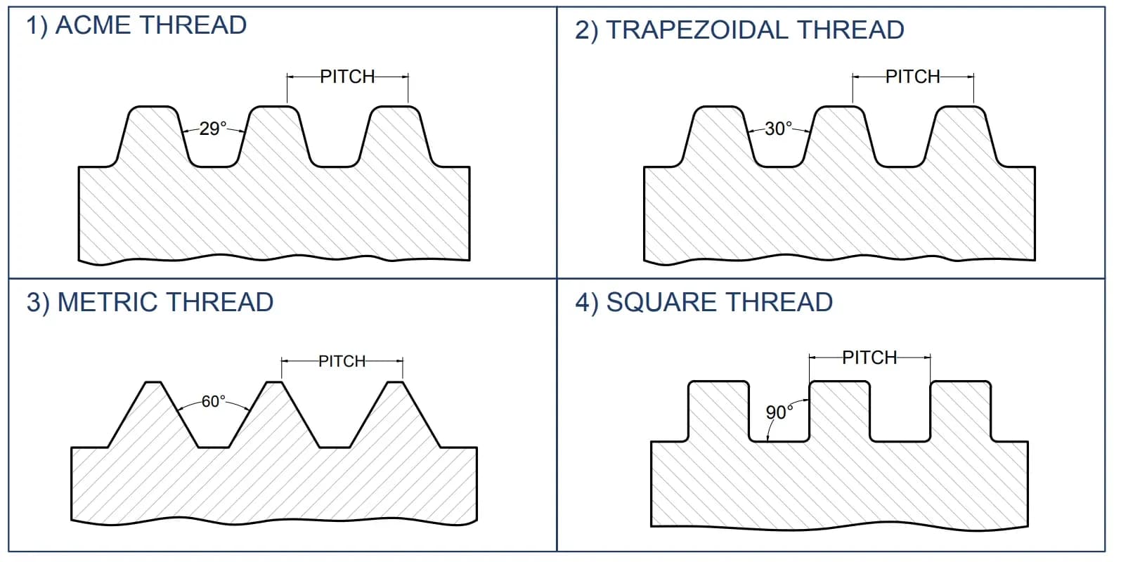
Thread geometry balances power efficiency, load capability, precision and manufacturing cost.
- Acme thread (29° angle): standard profile in imperial regions for power transmission, jacks and machinery adjustments.
- Trapezoidal thread (30° angle): the metric industrial standard across global automation, offering high shear strength and smooth nut engagement.
- Metric thread (60° angle): used in smaller precision instruments, light positioning or general fastening applications.
- Square thread (90° angle): delivers higher mechanical efficiency due to zero radial force, but is more difficult to manufacture and harder to compensate for wear.
Apex leadscrews are made with trapezoidal and ACME threads, and as square thread leadscrews.
Practical tip: If replacing an existing screw, visually inspecting threads is not enough. Verify pitch, thread angle and profile standard before ordering to avoid fitment issues.
Step 5: Differentiate between pitch and lead
Pitch and lead are fundamental parameters that dictate linear speed and motor sizing.
- Pitch (P): the axial distance between adjacent thread crests.
- Lead (L): the axial distance the nut travels along the screw during one complete 360° revolution.
- Single-start screw: lead = pitch (e.g. 2 mm pitch = 2 mm linear travel per turn).
- Double-start screw: lead = pitch × 2 (e.g. 2 mm pitch = 4 mm linear travel per turn).
- Four-start screw: lead = pitch × 4 (e.g. 2 mm pitch = 8 mm linear travel per turn).
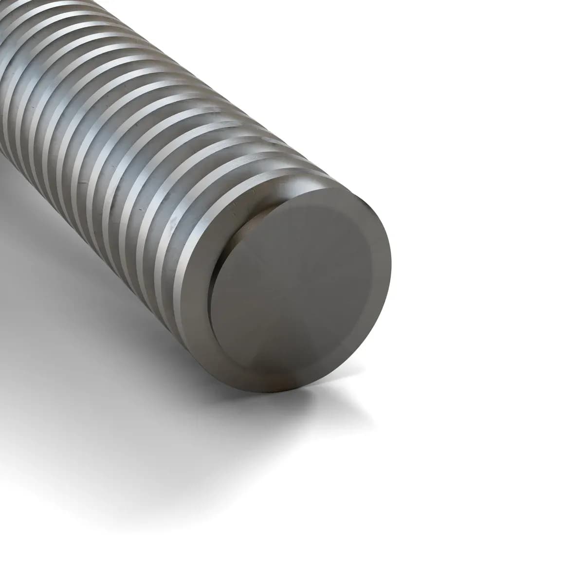 Single start: Ø20, pitch 4 mm, lead 4 mm
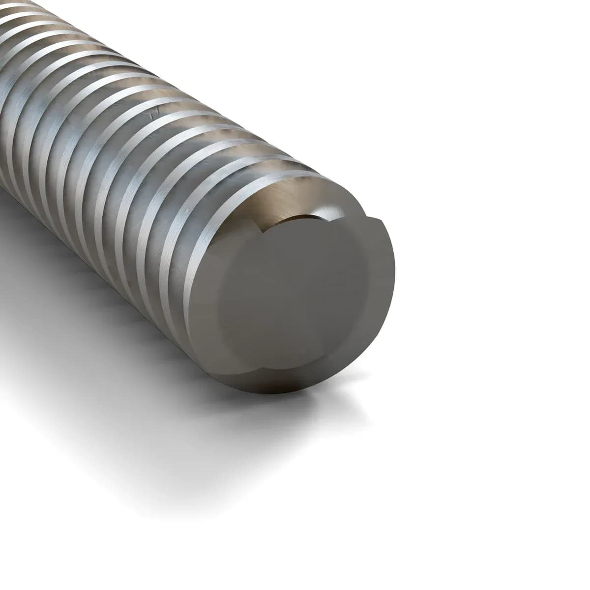 Two starts: Ø8, pitch 2 mm, lead 4 mm
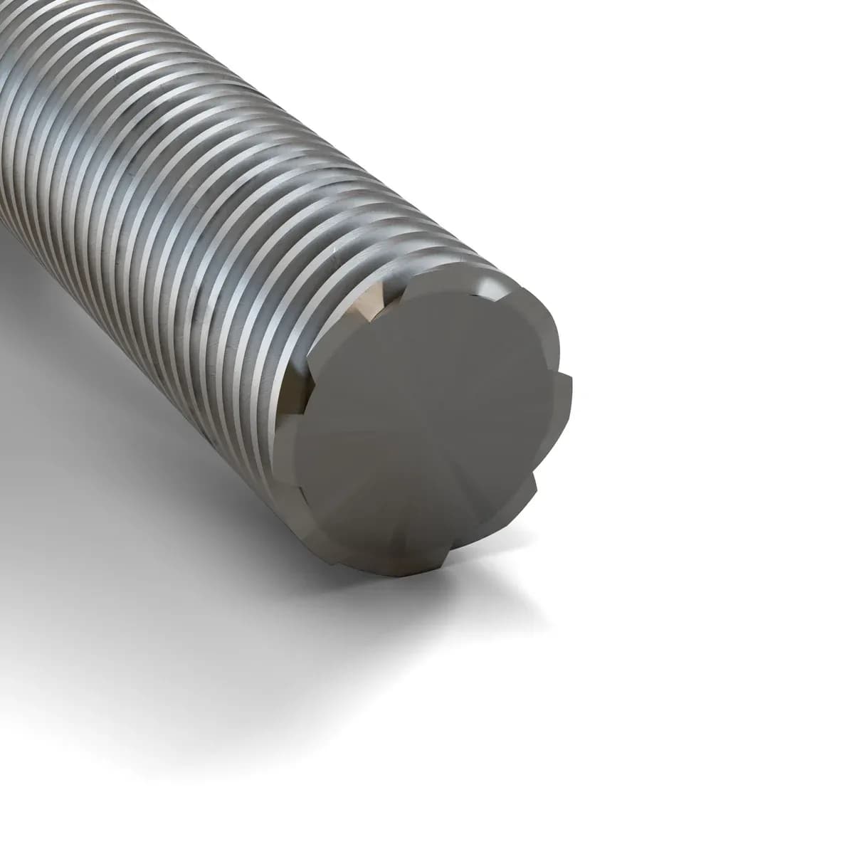 Eight starts: Ø16, pitch 2 mm, lead 16 mm
Multi-start screws achieve rapid linear movement at lower motor RPMs. However, higher leads lower mechanical advantage and increase the risk of back-driving under vertical loads. See Apex multi-start leadscrews.
Practical tip: Calculate the exact distance your machine must move per motor revolution before choosing single vs. multi-start geometry.
Step 6: Select the nut style and address backlash
The nut transfers force from the rotating shaft to the carriage. Choosing the wrong nut causes positioning drift, excessive clearance or premature binding.
Nut configurations
- Plain nut: compact and cost-effective where standard mechanical clearance is acceptable.
- Flanged nut: features a mounting flange for direct bolted attachment to machine tables.
- Anti-backlash nut: features a preloaded spring mechanism or split-nut design that eliminates axial play when reversing direction.
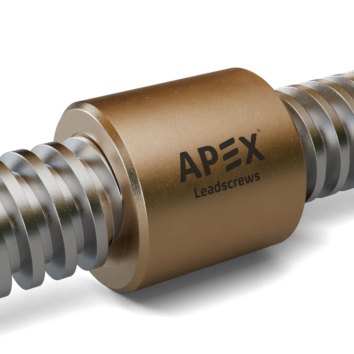 Plain (sleeve) nut, bronze
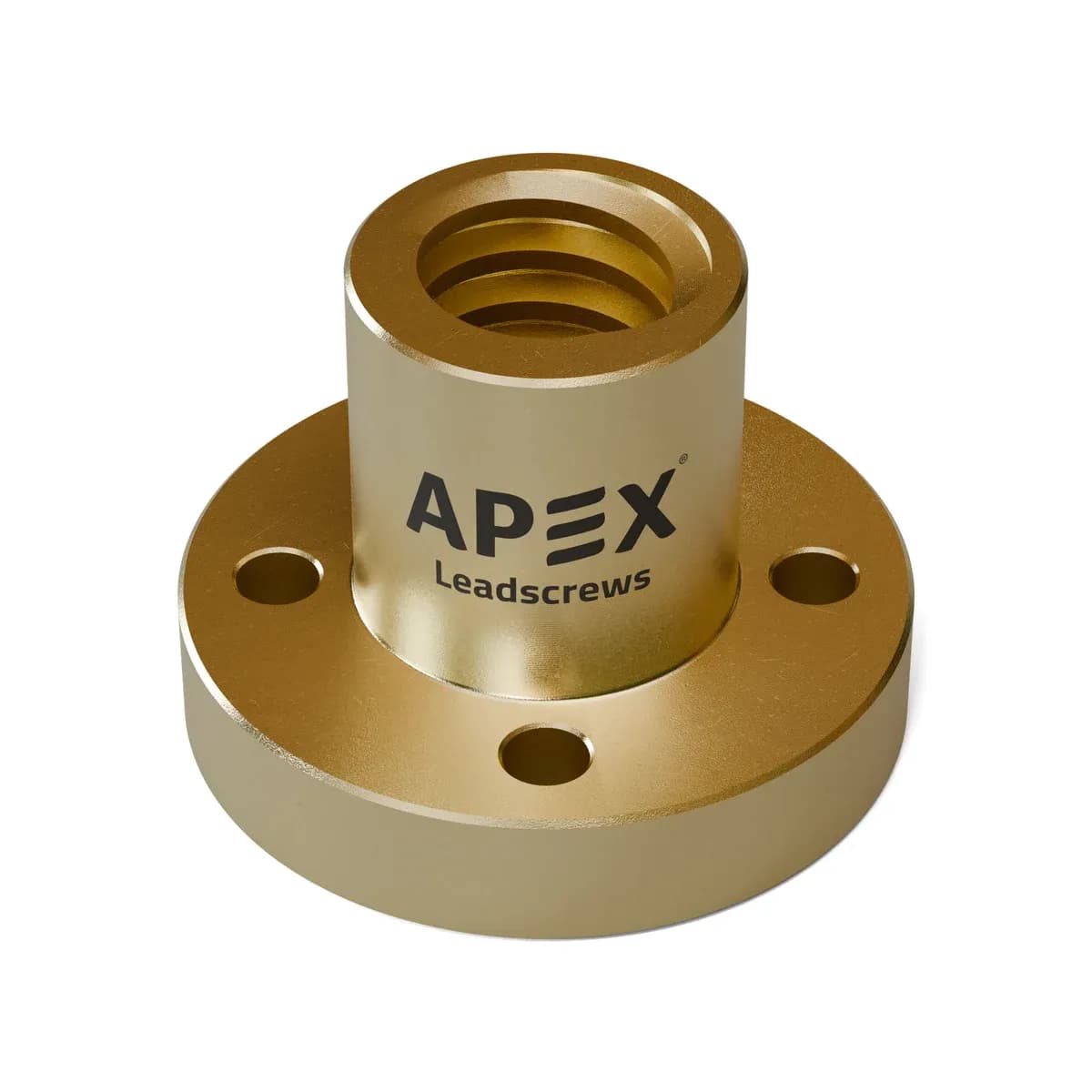 Flange nut, brass
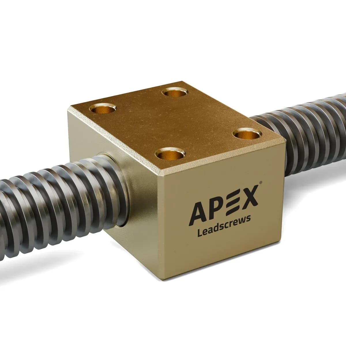 Block nut, brass
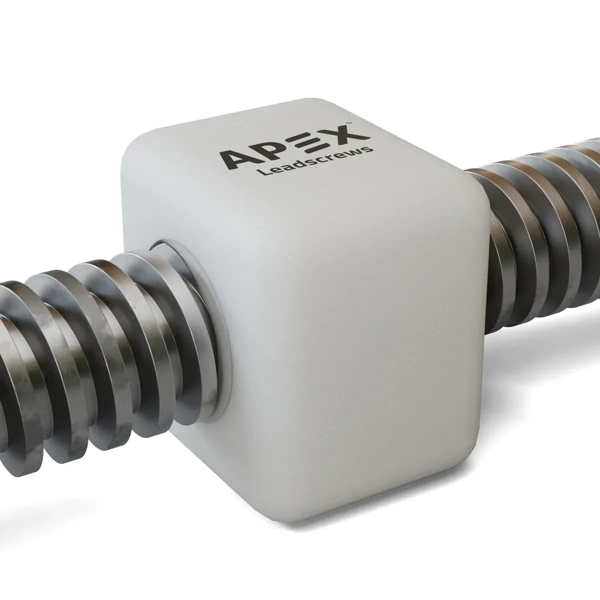 Block nut, Delrin (self-lubricating)
Backlash is the axial free play between screw and nut threads when motion reverses. If your CNC, 3D printer or inspection system reverses direction frequently and demands tight repeatability, an anti-backlash nut is essential.
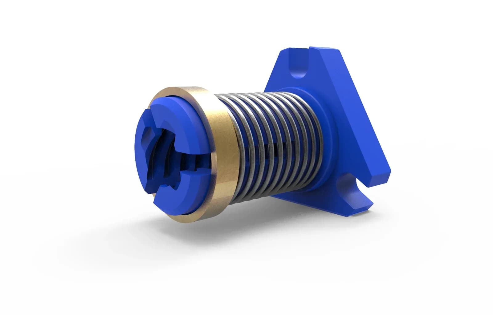
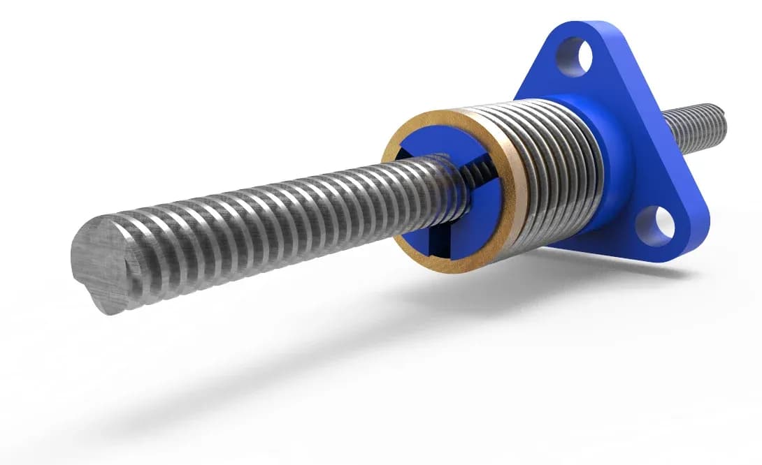
Practical tip: Communicate your exact positional tolerance to your supplier. Anti-backlash nuts increase drag torque slightly, which must be factored into motor selection.
All Apex nut types are on the leadnuts page.
Step 7: Check mounting, alignment and duty cycle
Even a correctly calculated lead screw will underperform or fail prematurely if misaligned.
- Support arrangement: fixed-free, fixed-supported or fixed-fixed bearing setups drastically alter critical rotational speed and buckling limits.
- Alignment accuracy: misalignment between the lead screw axis and linear guide rails creates side loading, noise, high current draw and fast wear.
- Duty cycle and friction: high continuous speeds generate frictional heat. Ensure appropriate grease, oil or dry lubricants are specified for the duty cycle.
Practical tip: If your drive motor draws high current or makes grinding noises, re-check end-bearing alignment and guide rail parallelism before assuming the lead screw is defective.
Step 8: Evaluate manufacturing process vs. total operating value
How a thread is manufactured directly dictates its lead accuracy, surface finish, run-out and overall cost.
| Technical property | Thread forming (rolled) | Thread cutting (machined) | Thread grinding |
|---|---|---|---|
| Relative price | Lower | Medium | High / premium |
| Positional accuracy | Good | Better | Very precise |
| Profile finish | Smooth / accurate | Medium smooth | Extremely accurate |
| Shaft run-out | Medium (up to 0.1 mm) | Medium (up to 0.1 mm) | Very low (up to 0.03 mm max) |
| Pitch accuracy (per m) | 300 μm | 500 μm | 50 μm |
| Production time (1000 pcs) | 1–2 weeks | 2–4 weeks | 5–9 weeks |
| Compatible materials | MS, EN8, SS303, SS304, SS316 | EN8, EN19, WPS, EN24, SS303, SS304, SS410, SS420 | All ferrous and hardened metals |
Practical tip: Don't buy thread-ground lead screws if standard thread rolling satisfies your accuracy budget. Likewise, don't compromise precision on a medical machine to save upfront costs. Focus on total operating value.
Summary: top 8 lead screw selection mistakes to avoid
- Choosing diameter based strictly on existing parts without recalculating load and buckling limits.
- Confusing thread pitch with linear lead movement.
- Overlooking unsupported shaft length and critical speed limits.
- Selecting a standard nut when reversal positioning requires anti-backlash technology.
- Ignoring duty cycle and thermal build-up during continuous high-speed runs.
- Neglecting shaft-to-guide rail alignment during installation.
- Assuming all thread profiles with similar appearances are interchangeable.
- Evaluating vendors purely on initial price rather than long-term precision and technical support.
Not sure which lead screw you need?
At Apex Leadscrews by Malkar Industries, we believe our responsibility goes far beyond manufacturing precision hardware. Whether you have a fully finalized production drawing or an unidentified motion problem on an existing machine, our engineering team is here to help. Even if you don't buy from us, you can reach out to us for technical guidance and engineering evaluation.