
Diamond Knurling: Complete Guide to Types, Methods, Tools and Applications

On This Page
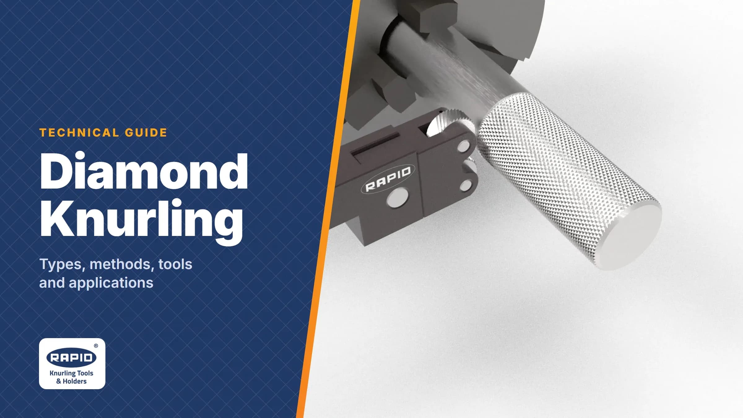
Diamond knurling is a mechanical surface-finishing process used to create a cross-hatched pattern of diamond-shaped projections or grooves on a cylindrical component. It is widely used where a component requires improved grip, friction, mechanical retention or an attractive surface finish.
The diamond pattern is produced by combining two opposing knurling directions, typically at 30° or 45°, depending on the required profile and application. For industrial production, selecting the correct knurling method, wheel profile and tool holder is critical for achieving a consistent pattern and controlling component deformation.
Typical Diamond Knurling Applications
Diamond knurling is used across a wide range of engineering and industrial products, including:
- Handles and knobs
- Control components
- Automotive components
- Machine components
- Tool handles
- Door handles
- Instrument components
- Watch and precision components
- Plastic moulding inserts
- Mechanical retention applications
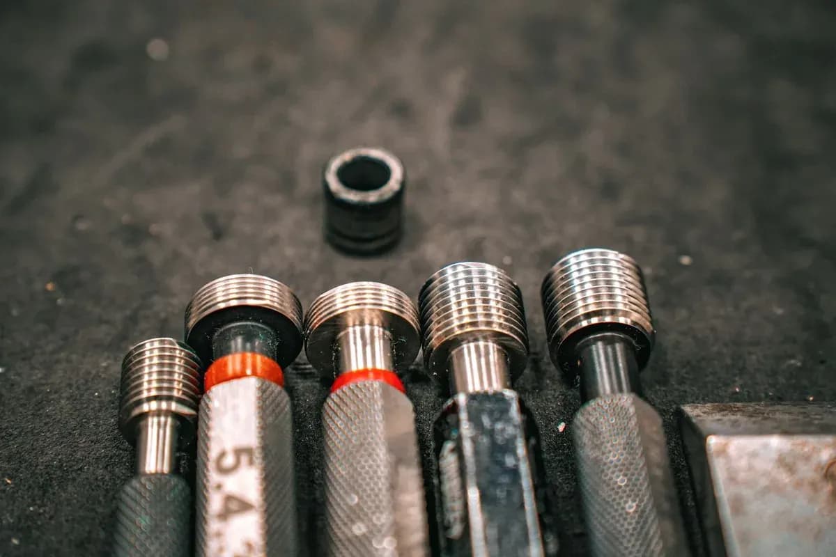 Instrument components: thread gauges with diamond-knurled handles. Photo: Yetkin Agaç / Pexels
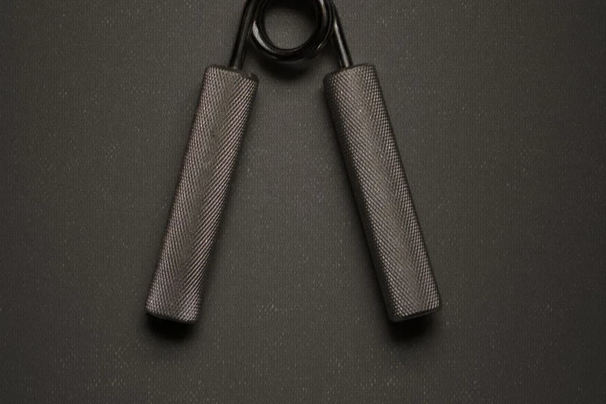 Handles: a hand gripper with diamond-knurled metal grips. Photo: Bill Bistak / Pexels
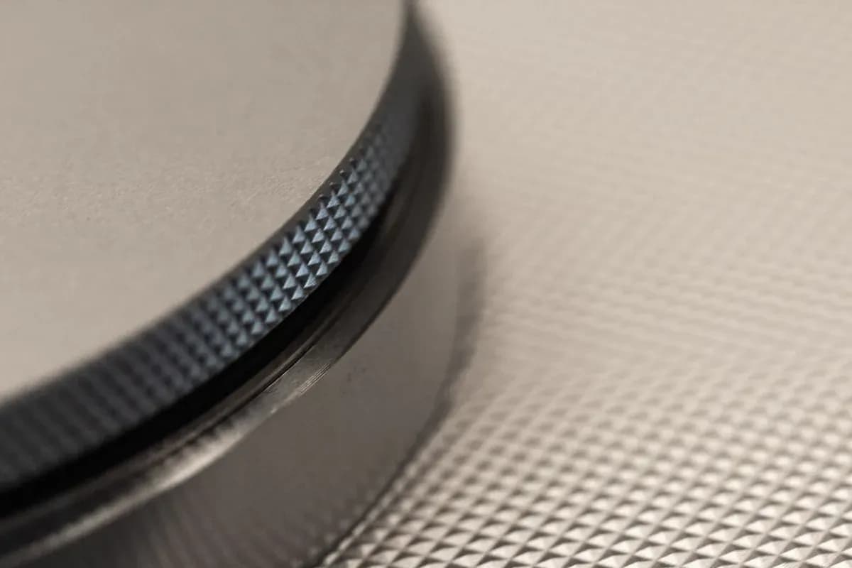 Knobs and control components: a diamond-knurled control ring. Photo: Oliver Dohrn / Pexels
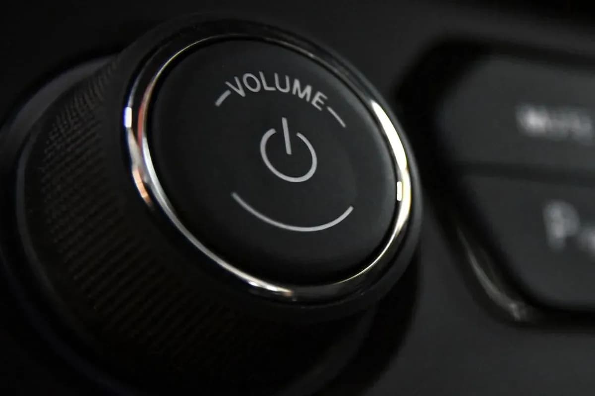 Automotive components: a car volume knob with a fine diamond knurl. Photo: Adonyi Foto / Pexels
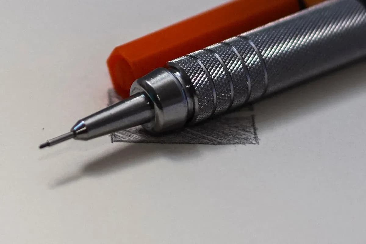 Precision components: a mechanical pencil with a diamond-knurled grip. Photo: japy / Pexels
Form Knurling vs. Cut Knurling
Form knurling: the F204 double-wheel holder feeds along the bar, pressing the diamond pattern into the surface.
Cut knurling: the C201 holder cuts the pattern, producing chips.
| Feature | Form Knurling | Cut Knurling |
|---|---|---|
| Principle | Material is plastically displaced | Material is removed by cutting |
| Chip generation | No conventional chips | Produces chips |
| Radial force | Higher | Lower |
| OD change | Material displacement can increase OD | Minimal OD change |
| Machine loading | Higher | Lower |
| Thin-wall components | Application dependent | Particularly suitable |
| Long knurling length | More difficult | Well suited |
| Surface finish | Good | High precision / finish possible |
| Typical application | General-purpose knurling | Thin, long, delicate or dimension-sensitive components |
Form knurling is versatile and produces a wide range of profiles. Because material is displaced, the starting diameter must be considered carefully. Cut knurling removes material and therefore produces significantly less dimensional displacement.
Rapid Diamond Knurling Tool Holders
Rapid offers several holder configurations for different component geometries, machine types and knurling requirements.
Form Knurling Holders
| Holder | Configuration | Machine | Main Application / Advantage |
|---|---|---|---|
| F101 | Single wheel | Lathe | Fast and precise plunge knurling |
| F102 | Single wheel | CNC | Fast and precise plunge knurling |
| F103 | Single wheel | CNC | Form knurling for CNC applications |
| F104 | Double wheel | Turret machine | Balanced form-knurling configuration |
| F102 Mini | Compact holder | Swiss / Sliding Head | Compact and small-component applications |
| F204 | Double wheel | CNC | Plunge and feed knurling; self-centering mechanism |
| F205 | Double wheel | CNC | Double-wheel form knurling configuration |
Cut and Straddle Knurling Holders
| Holder | Configuration | Machine | Main Application / Advantage |
|---|---|---|---|
| C210 | Double wheel | CNC | Cut knurling; low spindle load; excellent finish |
| C211 | Double wheel | CNC | Cut knurling; suitable for long knurling lengths |
| S201 | Straddle, double wheel | Turret machine | Small wall-thickness components |
| S214 | Straddle, double wheel | CNC | Small diameter and long-length components |
| S206 | Straddle, double wheel | Sliding Head | Small-diameter, long components with reduced bending tendency |
| M301 | Three-wheel | CNC | Three-wheel configuration for specialised applications |
| M602 | Six-wheel | Lathe | Multiple pitch/configuration options; reduced tool-change time |
Rapid Holder Selection at a Glance
| Application Requirement | Recommended Holder Type | Suitable Holders |
|---|---|---|
| General plunge diamond knurling | Single-wheel form | F101 / F102 / F103 |
| Compact / Swiss machine | Mini form holder | F102 Mini |
| Plunge + feed knurling | Double-wheel form | F204 |
| CNC form knurling | Double-wheel form | F204 / F205 |
| Long knurling length | Cut knurling | C210 / C211 |
| Thin-wall component | Straddle / Cut | S201 / S214 / S206 / C210 |
| Small diameter + long component | Straddle | S214 / S206 |
| Very small diameter | Cut knurling | C210 / C211 |
| Reduced spindle loading | Cut knurling | C210 / C211 |
| Multiple pitch availability | Multi-wheel holder | M301 / M602 |
Important: Final holder selection should be confirmed against the component diameter, knurling length, material, pitch, profile, machine configuration and required knurling method.
When Should You Use Straddle Knurling?
Straddle knurling is particularly useful when conventional radial knurling causes excessive bending or deflection. The component is positioned between opposing knurling wheels, providing a more balanced loading arrangement.
It is especially useful for:
- Small-diameter shafts
- Long components
- Thin-wall components
- Slender components
- Applications where component bending is a concern
When Should You Use Cut Knurling?
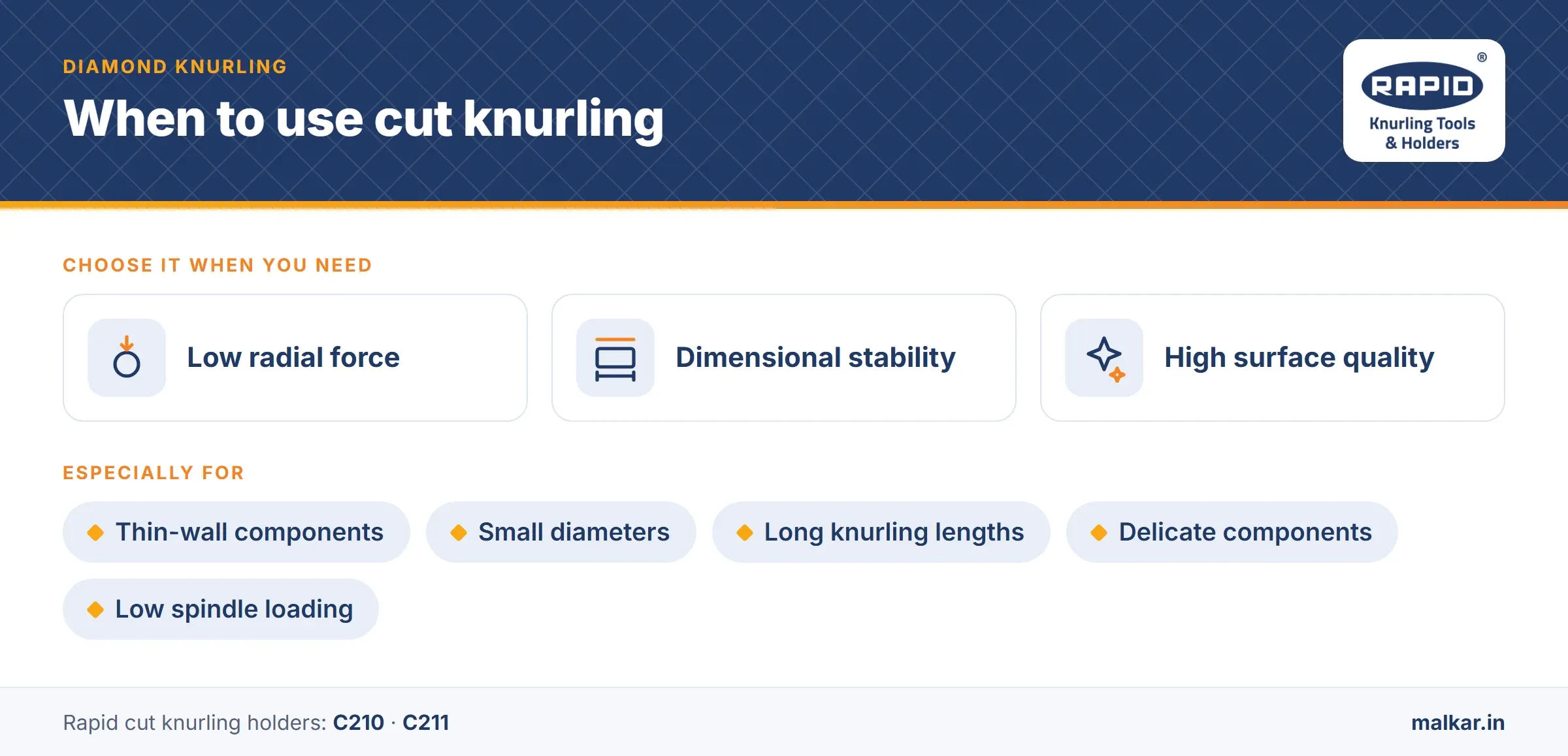
Cut knurling should be considered when low radial force, dimensional stability and surface quality are important. It is particularly useful for thin-wall components, small diameters, long knurling lengths, delicate components and applications where spindle loading must be minimised.
How to Select the Correct Rapid Knurling Tool
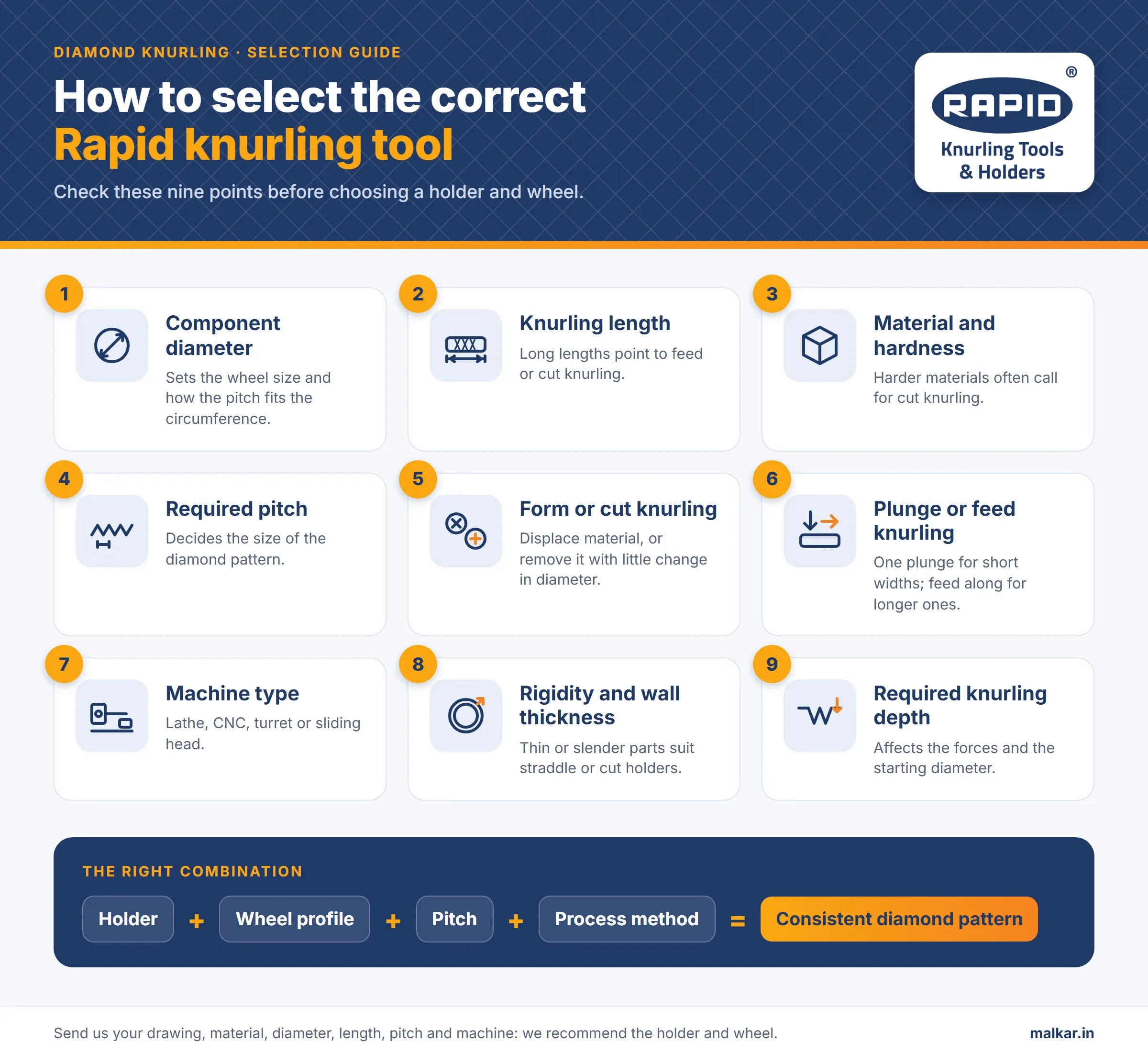
- Component diameter
- Knurling length
- Workpiece material and hardness
- Required pitch
- Form or cut knurling
- Plunge or feed knurling
- Machine type
- Component rigidity and wall thickness
- Required knurling depth
The correct combination of holder + wheel profile + pitch + process method is essential for producing a consistent diamond knurling pattern.
Rapid Knurling Tool: Application Engineering
There is no single knurling holder that is ideal for every component. Rapid Knurling Tool provides different holder configurations for conventional lathes, CNC turning machines and sliding-head machines, including form, cut and straddle knurling solutions.
If you are unsure which holder or wheel is suitable for your application, send us your component drawing, material, diameter, knurling length, pitch and machine details. Our technical team can recommend the appropriate Rapid knurling holder and wheel combination.
Rapid Knurling Tool: Engineered Knurling Solutions for Precision Manufacturing
Not sure which holder suits your component?
Send us your component drawing, material, diameter, knurling length, pitch and machine details. Our technical team will recommend the right Rapid holder and wheel combination.