
Understanding Knurling: What It Is and Why It Matters in Manufacturing

On This Page
What is Knurling?
Knurling is a specialised machining process which is mainly used for gripping applications. The process involves impressing a series of straight, angled, or crossed lines into a material's surface, usually through a lathe operation. The resulting patterns, called knurls, serve both functional and aesthetic purposes across the automotive, aerospace, and consumer goods sectors.
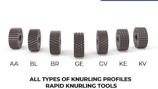
Types of Knurling Patterns
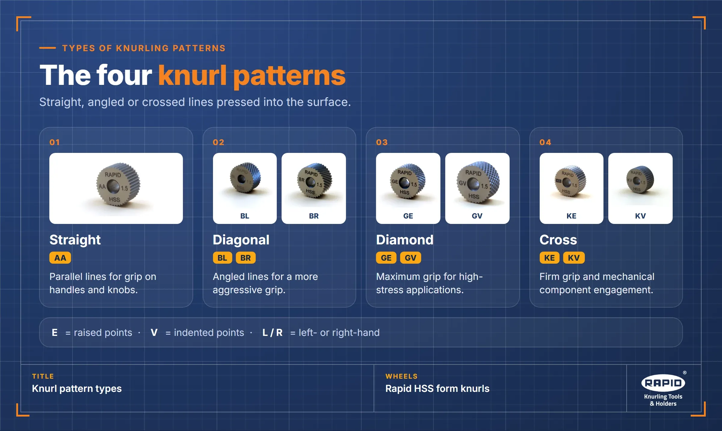
Four primary categories of knurling pattern exist.
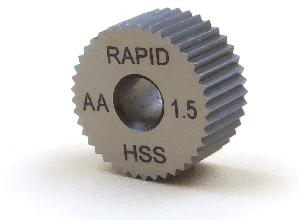
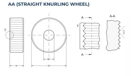
1. Straight Knurling (AA)
Creates parallel lines for grip enhancement on handles and knobs.
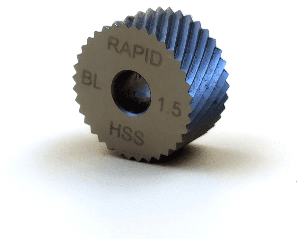
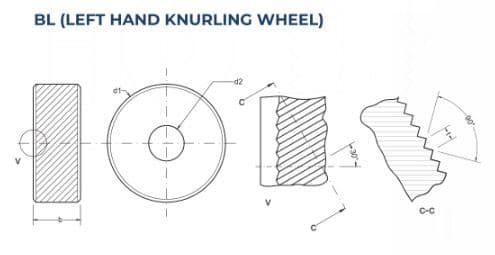
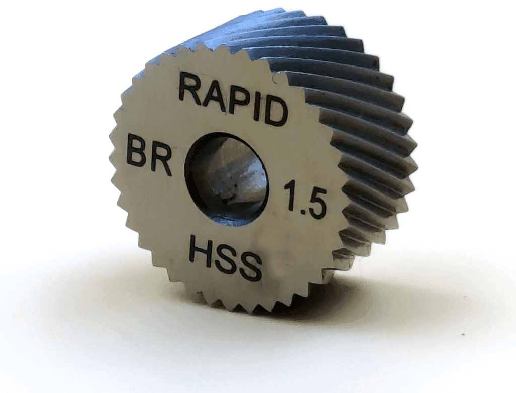
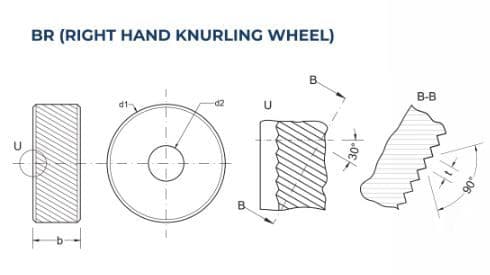
2. Diagonal Knurling (BL & BR)
Features angled lines for a more aggressive grip.
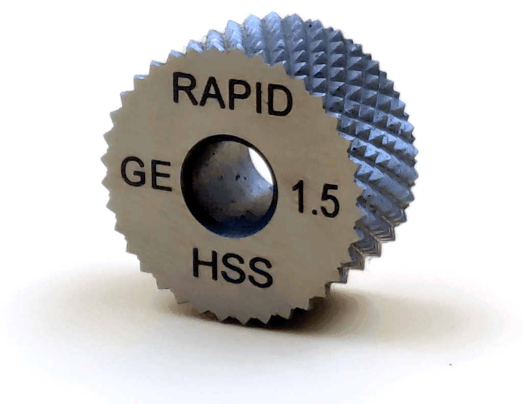
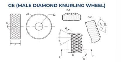
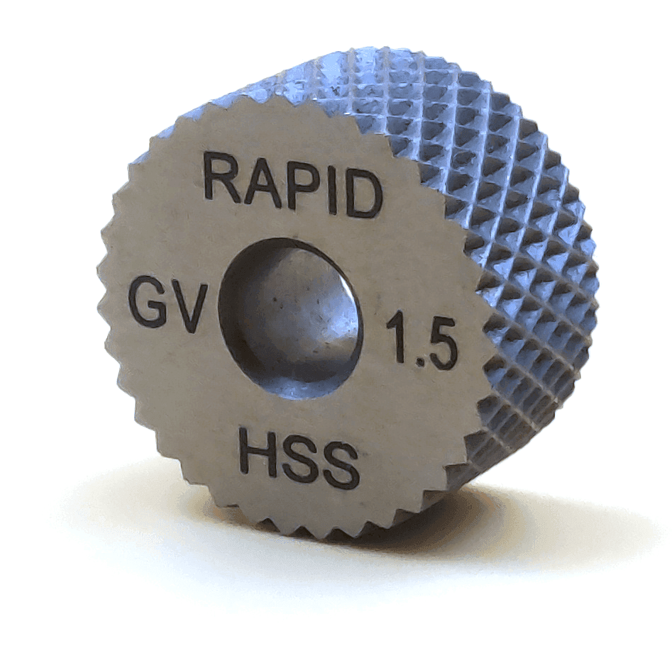
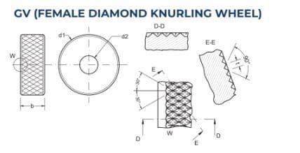
3. Diamond Knurling (GE & GV)
Provides maximum grip for high-stress applications.
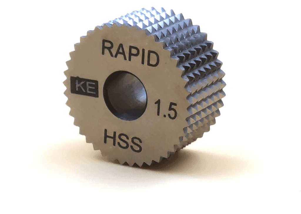
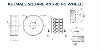
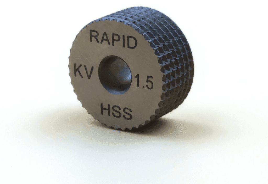
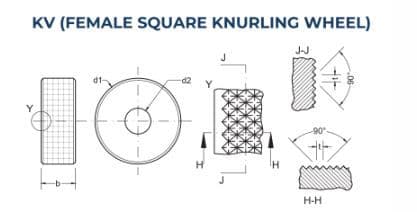
4. Cross Knurling (KE & KV)
Ensures firm grip and mechanical component engagement.
Knurling Wheel Features
Rapid Knurling Tools wheels feature:
- Run-out Accuracy: excellent dimensional consistency through face and outer diameter precision
- Material and Heat Treatment: constructed from high-speed steel with specialised heat treatment ensuring uniform hardness and extended tool life
- Sharp Edge Profiles: milled profiles enhance performance on ferrous and non-ferrous materials
- Size Variety: available in dimensions like 10x04x04 and 15x04x04, with pitches ranging from 0.4mm to 2.5mm; custom sizes available on request
Tooth Form and Technical Specifications

1. Tooth Form: Knurled teeth are generally V-shaped, with the depth of the tooth being less than that of a theoretical V-form. Features include a rounded root and crest; standard 90° angles, with custom 80° and 60° options available.
2. Circular Axial Pitch: the distance between consecutive teeth in millimetres, determining knurl spacing along the workpiece surface.
3. TPI (Teeth Per Inch): the number of teeth per linear inch, calculated as TPI = 1 / Circular Axial Pitch, affecting the final texture and grip characteristics.
4. Diametral Pitch: calculated as workpiece teeth divided by theoretical blank diameter, ensuring pattern compatibility with workpiece dimensions.
Knurling Methods
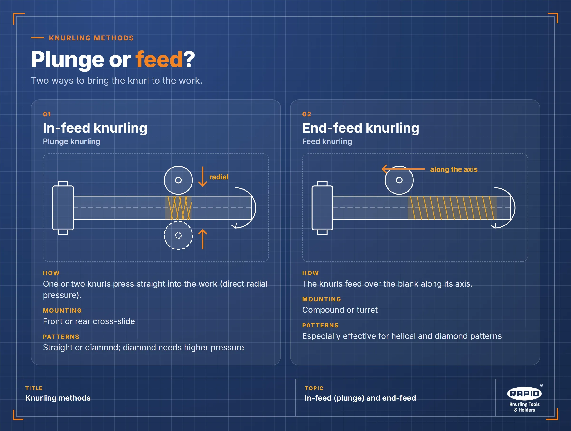
In-Feed Knurling (Plunge Knurling)
One or two knurls apply direct pressure via front or rear cross-slide mounting, suitable for straight or diamond patterns, though diamond variants require greater pressure loads.
End-Feed Knurling
Knurls feed over the blank via compound or turret mounting, particularly effective for helical and diamond patterns.
Speed & Feed Considerations
Optimal results require adherence to material-specific speed and feed rates:
- Steel (up to 600 N/mm²): for workpieces under 10mm diameter, cutting speeds of 25–55 m/min with radial feed of 0.04–0.08 mm/rev
- Aluminum: for parts up to 50mm diameter, cutting speeds of 30–65 m/min with radial feed of 0.04–0.08 mm/rev
Common Knurling Challenges and Solutions
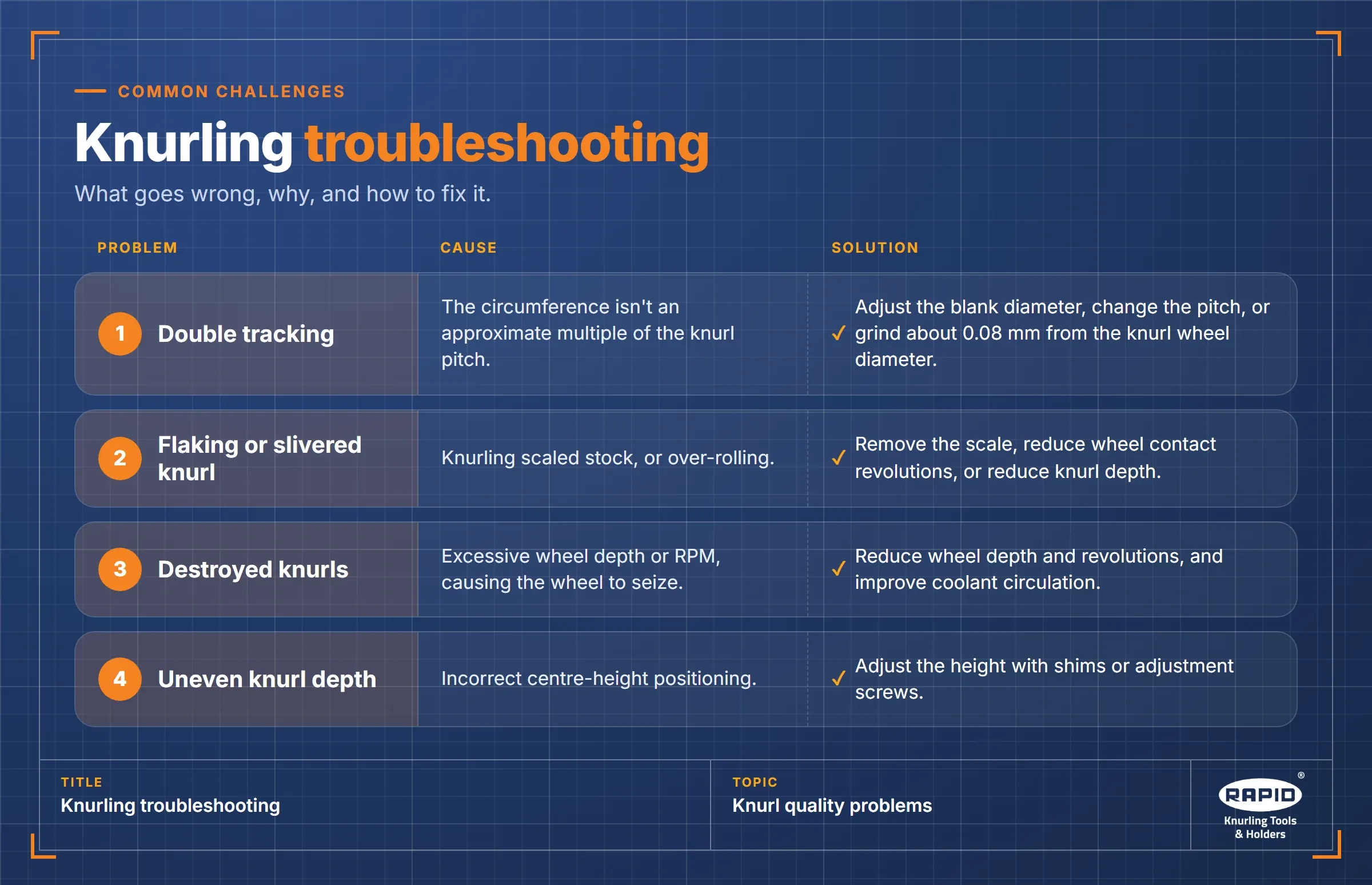
- Double Tracking: Cause: circumference isn't an approximate multiple of knurl pitch. Solution: adjust blank diameter, modify pitch, or grind approximately 0.08mm from the knurl wheel diameter.
- Flaking or Slivered Knurling: Cause: knurling scaled stock or over-rolling. Solution: remove scale, reduce wheel contact revolutions, or reduce knurl depth.
- Destruction of Knurls: Cause: excessive wheel depth or RPM causing wheel seizure. Solution: reduce wheel depth and revolutions, and improve coolant circulation.
- Uneven Knurl Depth: Cause: improper center-height positioning. Solution: adjust height using shims or adjustment screws.
Conclusion
Beyond surface treatment, knurling is a process that adds value to products by improving functionality, safety, and aesthetics. Manufacturers can achieve precision and consistency across materials using the appropriate tools and technical knowledge.