
Why Draft Is Non-Negotiable: Balancing Shrinkage in New Product Development

Brought to you by
Mascot Plastic Industries
A precision plastic injection molding manufacturer and Malkar channel partner, specializing in engineering-grade polymers and contract manufacturing.
On This Page
If you're in New Product Development (NPD), you know the friction that can happen when transitioning a beautiful 3D CAD model to a manufacturable tool design. At Mascot Plastic Industry, one of the most frequent conversations we have with NPD teams revolves around two intersecting forces: material shrinkage and draft angles.
When you're trying to achieve a sleek, modern aesthetic, adding tapers to your internal ribs and bosses might feel like a compromise. But understanding the thermomechanics at play inside the mold is the key to preventing tool modifications, part deformation, and costly delays.
The Physics of Cooling and Core Binding
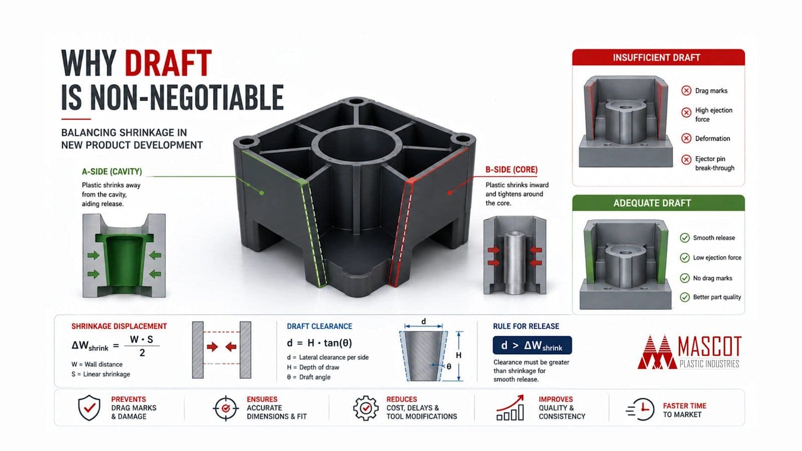
When molten plastic is injected into a chilled steel mold, it undergoes volumetric contraction as it solidifies. This shrinkage behaves differently depending on which side of the mold you're looking at.
- The Cavity (A-Side): As the plastic shrinks, it pulls away from the outer cavity walls. This actually aids the release of the cosmetic exterior.
- The Core (B-Side): This is where the challenge lies. As the plastic shrinks inward, it tightens around the internal steel core, ribs, and bosses, acting like a vise grip.
This is why draft angles (vertical tapers added to the part's walls) are critical. If we don't offset that "death grip" with enough draft, the ejection system has to apply massive force to push the part off the core. This leads to deep drag marks (galling), stressed plastic, warped geometry, or ejector pins punching right through the part.
The Engineering Calculations
To ensure a clean release, the lateral clearance () created by your draft angle must exceed the inward distance the material shrinks ().
1. Calculating Shrinkage Displacement
First, we determine how far the material will pull inward against the core.
- = The nominal width or distance between opposing internal walls (mm)
- = The material’s linear shrinkage rate (expressed as a decimal coefficient)
2. Calculating Draft Clearance
Next, we calculate the lateral breathing room generated by a specific draft angle over the depth of the draw.
- = Lateral clearance / draft offset per side (mm)
- = Depth of draw / vertical feature height (mm)
- = Draft angle (degrees)
The Rule for Release: For immediate kinetic release without galling, the clearance geometry must satisfy the static friction boundary:
Material Selection Changes Everything
Different polymer structures dictate how aggressive your draft needs to be. Amorphous resins shrink predictably and uniformly, allowing for tighter packaging. Semi-crystalline resins pack denser as they cool, leading to higher shrinkage and requiring more aggressive drafting.
Here are the baseline guidelines we use at Mascot for common NPD materials:
| Polymer Family | Structure | Typical Linear Shrinkage (S) | Min. Draft (Smooth Core) | Recommended Draft |
|---|---|---|---|---|
| PC / ABS | Amorphous | 0.004 – 0.007 | ||
| Polycarbonate (PC) | Amorphous | 0.005 – 0.008 | ||
| Polypropylene (PP) | Semi-Crystalline | 0.012 – 0.022 | ||
| POM (Acetal) | Semi-Crystalline | 0.018 – 0.025 | ||
| Nylon (PA66 unfilled) | Semi-Crystalline | 0.010 – 0.025 | ||
| Glass-Filled Nylon | Anisotropic | Flow: 0.003 / Cross: 0.011 |
DFM Modifiers for the Real World
While those formulas work for smooth steel, real-world tooling often requires adjustments:
- Surface Texture Compensation: Textured cavity steel creates microscopic mechanical undercuts. The draft must increase linearly based on texture depth. Add of draft for every () of peak-to-valley texture depth.
- Sink Mark Mitigation: To prevent thermal sinks on the cosmetic A-side, internal B-side ribs must maintain strict dimensional ratios while incorporating draft. Ensure the base of a drafted rib does not exceed 50-60% of the adjoining outer wall thickness.
- Anisotropic Fiber Orientation: Glass-filled (GF) polymers shrink significantly less parallel to the flow vector, and more perpendicular to it. We often use mold-flow analysis to map gate locations to ensure critical un-drafted shutoffs align parallel to the flow, mitigating high transverse shrinkage.
By integrating these draft and shrinkage calculations early in the CAD phase, NPD teams can ensure their designs are ready for rapid, high-yield manufacturing from day one.