
How to Prevent Creep and Fatigue Failure in Plastic Injection Molded Parts

Brought to you by
Mascot Plastic Industries
A precision plastic injection molding manufacturer and Malkar channel partner, specializing in engineering-grade polymers and contract manufacturing.
On This Page
Introduction
A plastic component may pass every dimensional inspection, withstand its initial load during testing, and perform perfectly when first assembled, yet still fail months or even years later.
Unlike metals, plastics do not simply respond to force based on their immediate strength. Their mechanical behavior changes over time. A plastic clip may gradually deform under a constant load, a housing may lose dimensional accuracy after prolonged stress, or a snap-fit may crack after thousands of opening and closing cycles.
These long-term behaviors are known as creep and fatigue, and they are among the most critical considerations when designing high-performance plastic components.
For industries such as automotive, medical devices, consumer electronics, and industrial equipment, understanding creep and fatigue is essential to ensuring long-term product reliability.
At Mascot Plastic Industries, these behaviors are evaluated during material selection, product design, and process optimization to manufacture plastic components that maintain their performance throughout their intended service life.
Plastic parts are often subjected to mechanical loads for years without replacement.
Examples include:
- Dashboard mounting brackets
- Electrical connectors
- Cable clips
- Snap-fit enclosures
- Medical device housings
- Appliance hinges
- Structural supports
- Pipe fittings
- Battery holders
Some components experience continuous loads, while others undergo repeated loading and unloading thousands, or even millions, of times.
Although the applied force may remain well below the material's ultimate strength, failure can still occur because plastics respond differently over time.
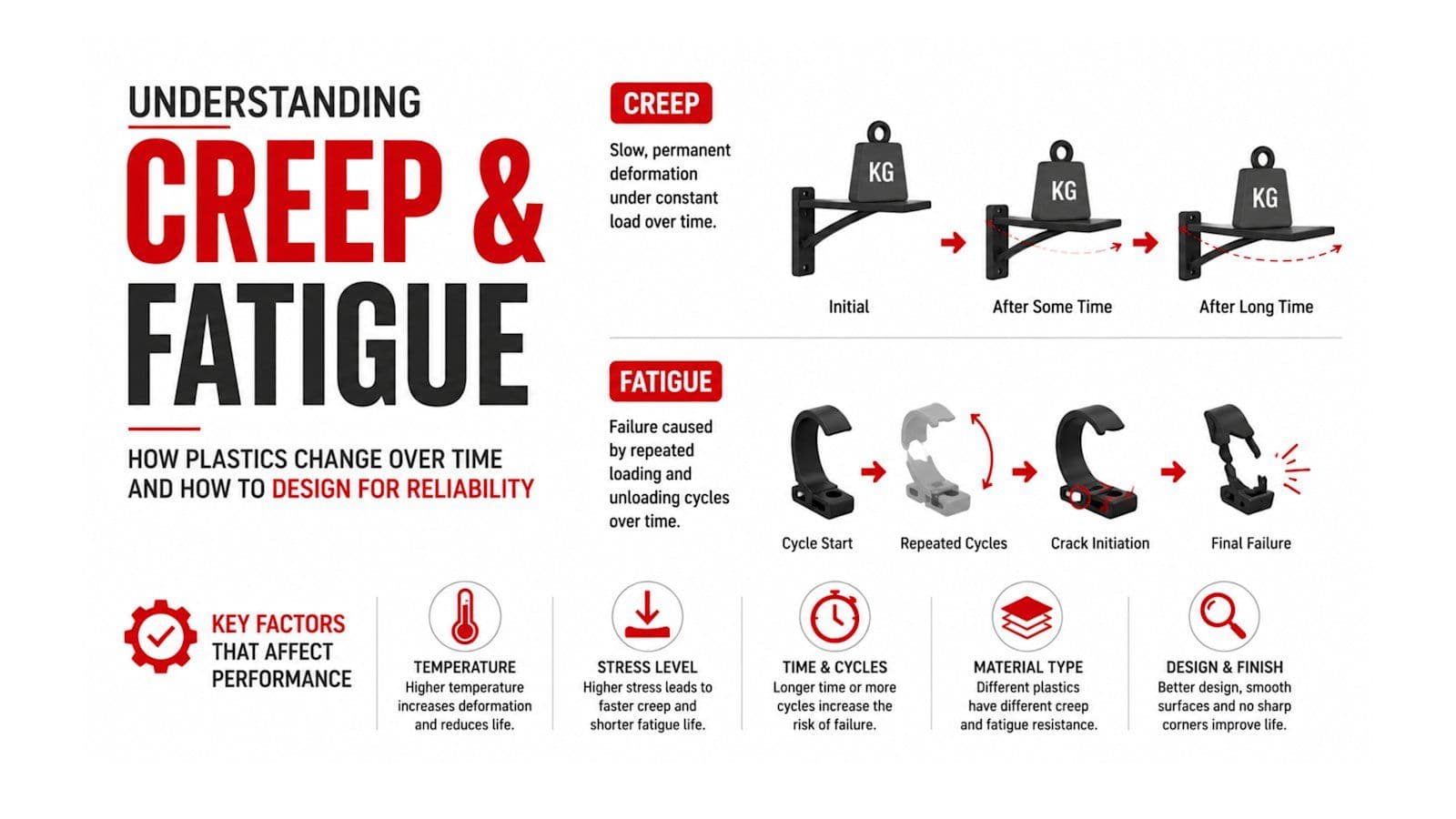
Creep is the slow, permanent deformation of a material when subjected to a constant load over an extended period.
Unlike immediate elastic deformation, creep continues even when the applied load does not increase.
Imagine placing a heavy object on a plastic shelf. Initially, the shelf bends slightly. Weeks or months later, it sags even further, despite the weight remaining unchanged.
That gradual deformation is creep.
Plastic polymers are made of long molecular chains.
Under continuous stress:
- Molecular chains slowly rearrange.
- Internal movement occurs within the polymer structure.
- Permanent deformation gradually develops.
Higher temperatures accelerate this process by increasing molecular mobility.
Several variables determine how much creep a plastic component will experience.
Material Type
Different polymers exhibit significantly different creep resistance.
Generally:
Better Creep Resistance
- Polycarbonate (PC)
- PBT
- PEEK
- PPS
- Glass-filled Nylon (PA GF)
Moderate Resistance
- ABS
- Acetal (POM)
Lower Resistance
- Polypropylene (PP)
- Polyethylene (PE)
Engineering plastics generally outperform commodity plastics in long-term dimensional stability.
Temperature
Temperature has a major impact on creep.
As temperature increases:
- Polymer chains move more freely.
- Deformation accelerates.
- Load-bearing capacity decreases.
A component that performs well at room temperature may creep significantly inside a vehicle exposed to summer heat.
Applied Stress
Higher loads produce faster creep.
Even small increases in stress can dramatically shorten component life.
Designers therefore try to keep operational stresses well below the material's allowable long-term stress.
Time
Creep is time-dependent.
A component may appear stable after:
- One day
- One week
Yet exhibit significant deformation after:
- Six months
- Five years
Product life requirements directly influence material selection.
Common examples include:
Automotive Dashboard Mounts
Continuous loading combined with elevated cabin temperatures can gradually distort plastic mounting brackets if the wrong material is selected.
Plastic Shelving
Heavy loads eventually produce permanent sagging.
Cable Clamps
Constant pressure around electrical cables slowly relaxes, reducing holding force.
Pipe Supports
Plastic brackets supporting piping systems may deform over years of continuous service.
Fatigue is a completely different failure mechanism.
Instead of constant loading, fatigue occurs because a component experiences repeated loading and unloading cycles.
Each individual load may be relatively small.
However, repeated stress gradually damages the material until cracks develop.
Eventually, sudden failure occurs.
Examples include:
- Opening and closing a storage compartment
- Pressing a control button
- Flexing a living hinge
- Engaging a snap-fit repeatedly
- Vibrating automotive components
A part that survives one operation may fail after hundreds of thousands of cycles.
Fatigue usually progresses through three stages.
Stage 1: Microcrack Formation
Tiny cracks begin forming around:
- Sharp corners
- Mold defects
- Weld lines
- Stress concentrators
These cracks are often invisible.
Stage 2: Crack Growth
Each loading cycle enlarges the crack.
The component still functions normally.
Stage 3: Sudden Failure
Once the crack reaches a critical size, the remaining material can no longer support the load.
The part fractures unexpectedly.
This is why fatigue failures often appear sudden, even though damage accumulated gradually over time.
Material Selection
Different polymers have varying fatigue performance.
Excellent fatigue resistance:
- Nylon (PA)
- Acetal (POM)
- PBT
- PEEK
Moderate:
- PC
- ABS
Lower:
- Standard PP
- PS
Stress Level
Reducing applied stress dramatically increases fatigue life.
Small reductions in stress often produce disproportionately large improvements.
Surface Quality
Scratches act as crack initiation sites.
Better surface finish generally improves fatigue resistance.
Weld Lines
Improper gate placement can create weld lines that weaken fatigue performance.
Scientific mold design minimizes these weak regions.
Fiber Orientation
Glass-filled plastics exhibit different fatigue behavior depending on fiber direction.
Optimizing flow orientation is therefore important during mold design.
| Property | Creep | Fatigue |
|---|---|---|
| Load Type | Constant | Repeated |
| Failure Cause | Gradual deformation | Crack growth |
| Time Dependent | Yes | Yes |
| Visible Before Failure | Usually yes | Often no |
| Common Result | Sagging, distortion | Sudden fracture |
| Typical Applications | Shelves, brackets, supports | Hinges, clips, snap-fits |
Although both involve long-term loading, they require different engineering solutions.
Several design strategies improve creep resistance.
Select Engineering Plastics
Materials such as:
- Glass-filled Nylon
- PBT
- PEEK
- PPS
maintain stiffness under prolonged loading.
Increase Wall Thickness
Thicker sections distribute stress over a larger area.
However, excessive thickness may create molding defects such as sink marks.
Balance is essential.
Add Structural Ribs
Properly designed ribs increase stiffness without significantly increasing weight.
Reduce Continuous Stress
Designing supports to distribute loads evenly minimizes creep deformation.
Control Operating Temperature
Heat accelerates creep.
Selecting heat-resistant materials is critical for under-hood and high-temperature interior applications.
Eliminate Sharp Corners
Sharp edges concentrate stress.
Adding generous radii distributes forces more evenly.
Optimize Gate Location
Balanced material flow reduces weld lines and improves structural integrity.
Improve Mold Cooling
Uniform cooling minimizes residual stress.
Residual stress significantly reduces fatigue life.
Select Fatigue-Resistant Materials
Materials with excellent fatigue properties maintain performance over millions of cycles.
Validate Through Testing
Repeated mechanical cycling verifies component durability before production.
Automotive and industrial manufacturers perform specialized testing to predict long-term performance.
Creep Testing
A constant load is applied for extended periods while measuring deformation over time.
Engineers evaluate:
- Permanent strain
- Dimensional stability
- Load retention
Fatigue Testing
Components are repeatedly loaded until failure.
Measurements include:
- Number of cycles to failure
- Crack initiation
- Crack propagation
- Ultimate fatigue life
These tests simulate years of real-world service within a controlled laboratory environment.
Modern Computer-Aided Engineering (CAE) tools allow engineers to predict creep and fatigue performance before manufacturing begins.
Finite Element Analysis (FEA) can estimate:
- Stress distribution
- Areas prone to creep
- Fatigue life
- Crack initiation zones
- Safety factors
Early simulation helps reduce design iterations, lower development costs, and improve product reliability.
Understanding long-term mechanical behavior is essential across many industries.
Automotive
- Dashboard clips
- HVAC components
- Battery mounts
- Door handles
- Seat mechanisms
Medical Devices
- Instrument housings
- Syringe components
- Drug delivery devices
- Surgical instrument handles
Consumer Electronics
- Laptop hinges
- Charging connectors
- Phone housings
- Wearable devices
Industrial Equipment
- Pump housings
- Electrical enclosures
- Pipe supports
- Machine guards
In all these applications, long-term reliability directly affects safety, performance, and customer satisfaction.
At Mascot Plastic Industries, designing durable plastic components involves far more than achieving initial strength. Our engineering team evaluates long-term loading conditions, service temperatures, environmental exposure, and expected product life before recommending materials and design solutions.
Through scientific mold design, optimized processing parameters, and the use of high-performance engineering polymers, we help customers minimize creep deformation and improve fatigue resistance in demanding applications. Combined with our 60,000 sq. ft. manufacturing facility, Class 10,000 Clean Room, and 40+ advanced injection molding machines, we manufacture precision plastic components that deliver consistent performance throughout their operational life.
Creep and fatigue are two of the most important, and often overlooked, mechanical behaviors affecting plastic components. A part that performs perfectly on day one may gradually deform under constant load or unexpectedly fail after years of repeated use if these phenomena are not considered during design.
By understanding how materials respond over time, selecting appropriate engineering polymers, optimizing component geometry, and validating performance through testing and simulation, manufacturers can significantly improve product durability and reliability.
At Mascot Plastic Industries, this long-term engineering perspective is integrated into every stage of product development, ensuring that plastic components are designed not only to meet today's requirements but also to perform reliably throughout years of real-world service.