
Bevel Gears
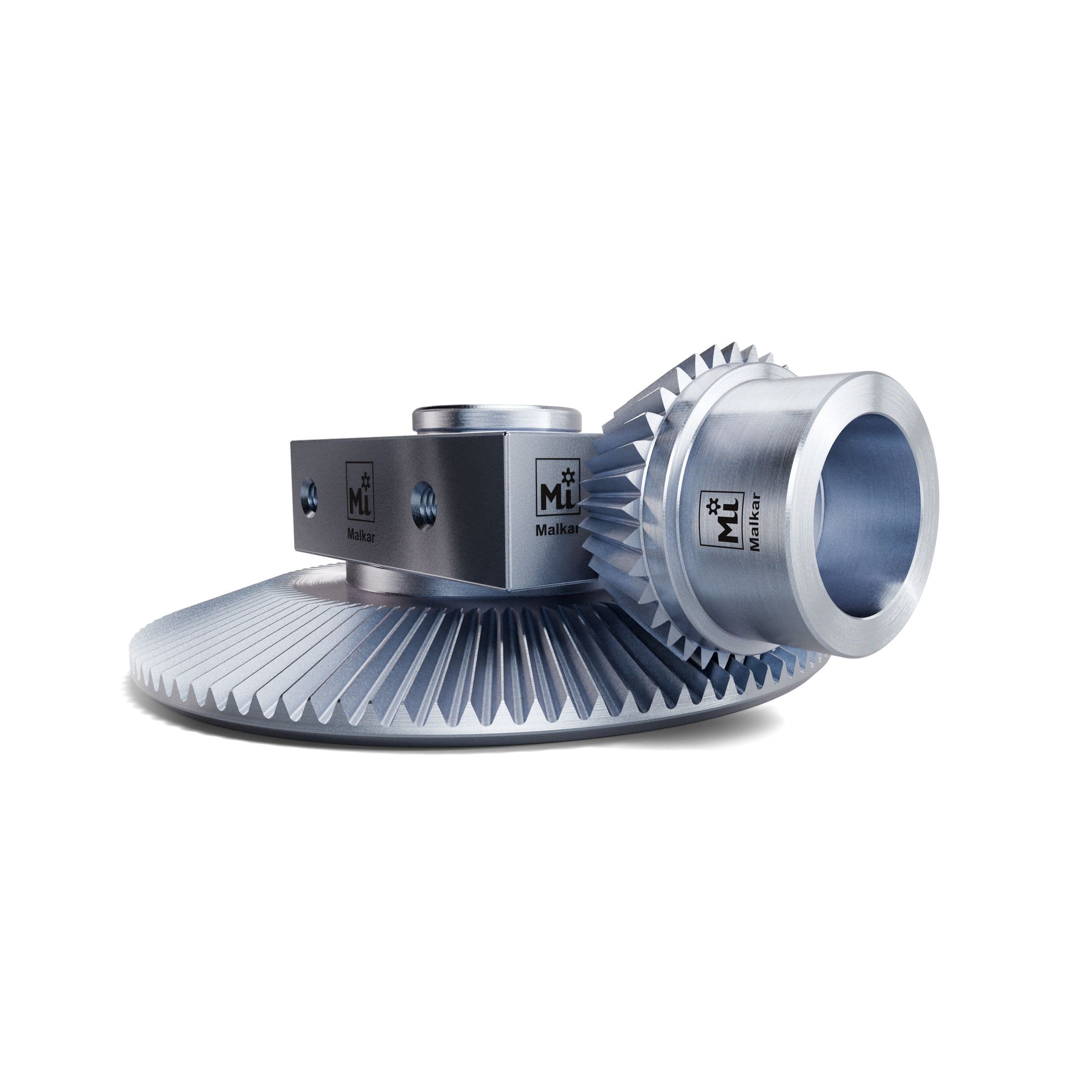
Bevel gears transmit power between intersecting shafts, most often at 90°. Malkar makes bevel gears and matched gear and pinion sets to your drawing: tooth data, bores, material, heat treatment and finish as specified.
Showing 1 of 1 Bevel Gears
Types of bevel gears
- Straight bevel gears: straight teeth that run towards the apex of the pitch cone. Simple to make and to mount, with low axial thrust; generally used at moderate speeds (pitch-line speeds up to about 5 m/s).
- Spiral bevel gears: curved, oblique teeth. More than one tooth is in contact at a time, so they run quieter and carry more load at high speed, at the cost of higher axial thrust that depends on the hand of spiral and the direction of rotation.
- Zerol bevel gears: curved teeth with a zero spiral angle. Smoother than straight teeth, with thrust loads similar to straight bevel gears.
- Miter gears: a pair of identical bevel gears with a 1:1 ratio, usually at 90°. They change the direction of a shaft without changing its speed.
- Hypoid gears: related to spiral bevel gears, but the shaft axes are offset and do not intersect; typical of vehicle rear axles.
Tell us which tooth form your design uses; the set shown on this page is a straight bevel set.
Bevel gear geometry in brief
Bevel gear sizes are given at the outer (heel) end of the teeth.
| Term | Meaning | Formula (shafts at 90°) |
|---|---|---|
| Module m | Tooth size at the heel | |
| Ratio i | Gear teeth / pinion teeth | i = z₂ / z₁ |
| Pitch diameter d | Diameter of the pitch cone at the heel | d = m × z |
| Pitch angle δ | Half-angle of the pitch cone | tan δ₁ = z₁ / z₂, δ₂ = 90° - δ₁ |
| Cone distance R | Apex to heel along the pitch cone | R = d / (2 sin δ) |
| Face width b | Length of the teeth along the cone | usually no more than R / 3 |
Example, our 98 : 35 set at module 1.5: pitch diameters 147 mm and 52.5 mm, pitch angles 70.35° and 19.65°, cone distance 78.05 mm.
Gear and pinion work as a pair
The pitch angles of a bevel gear depend on the tooth counts of both gears, so a bevel gear only meshes correctly with the pinion it was designed for. Gear and pinion are therefore made as a matched set, and the mounting distance of each is set at assembly to get the right tooth contact pattern and backlash. To replace one gear of a pair, we need the data of its mate, or both parts.
Materials and finish
Material, heat treatment and finish follow your drawing. Typical choices:
- Medium-carbon steels (EN8, EN9) for lightly loaded gears.
- EN19 alloy steel, hardened and tempered, for tough, wear-resistant gears; the set on this page is EN19.
- Case-carburising steels (EN353, 20MnCr5) for high loads and hard-wearing tooth surfaces.
- Stainless steel where corrosion matters; brass or engineering plastics for light, quiet drives.
- Finishes such as zinc plating or blackening against corrosion.
What to send for a quote
- Drawing (PDF or DWG) or the gear data: module or diametral pitch, number of teeth on the gear and the pinion, pressure angle, face width
- Shaft angle (if not 90°) and mounting distances
- Tooth form: straight, spiral, zerol
- Bore, keyway or spline and hub dimensions
- Material, heat treatment, hardness and surface finish
- Accuracy class, if specified
- Quantity
Use Enquire Now on the product page; you can attach your drawing.
Where it's used